A multiloop circuit is given in the figure below. The current I_1


Electronics, Free Full-Text
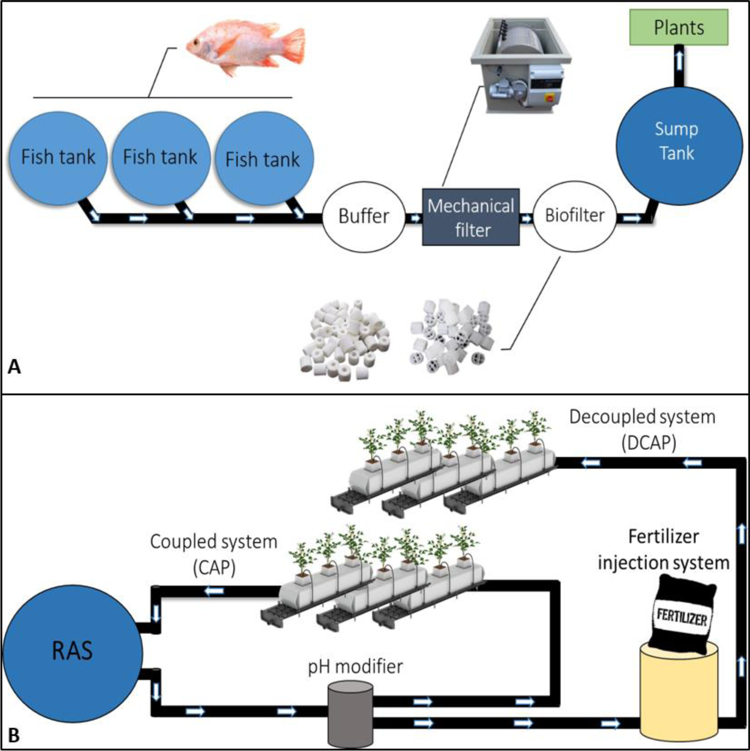
Basil functional and growth responses when cultivated via different aquaponic and hydroponics systems [PeerJ]

Two-Port Networks
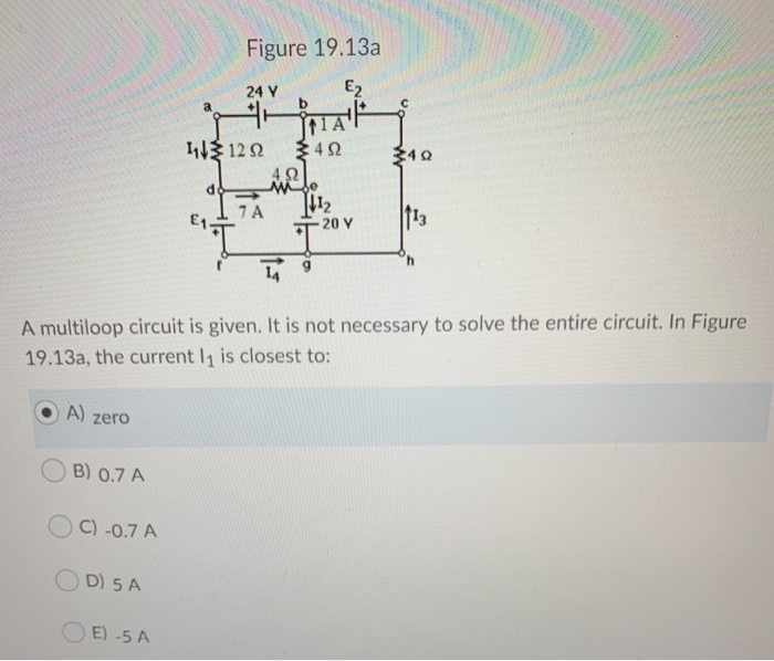
Solved Figure 19.13a 24 Y Ez b 340 11122 3422 4.92 Male 7A

Use Kirchhoff's rules to determine the currents I1, I2, and I3 for

Design of transient enhanced output-capacitor-less flipped voltage follower based LDO regulator with a fast control loop for wide range of capacitive loads - ScienceDirect

homework and exercises - Why am I getting negative current on the right loop of the Kirchhoff's circuit? - Physics Stack Exchange

In the circuit in the figure below, the voltage source V = 10.0 V

How to convert an electrical circuit into a system of linear equations and determine the currents I1, I2, and I3 and for the electrical subsystem network shown in the figure by using
Course: Physics, Topic: Unit 5: Kirchhoff's Laws and Electric Circuits
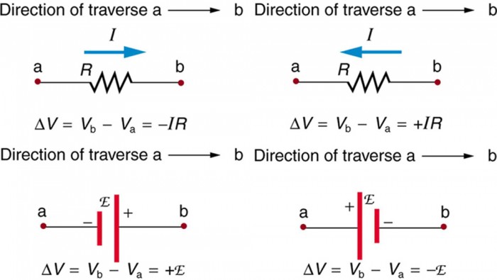
Kirchhoff's Rules